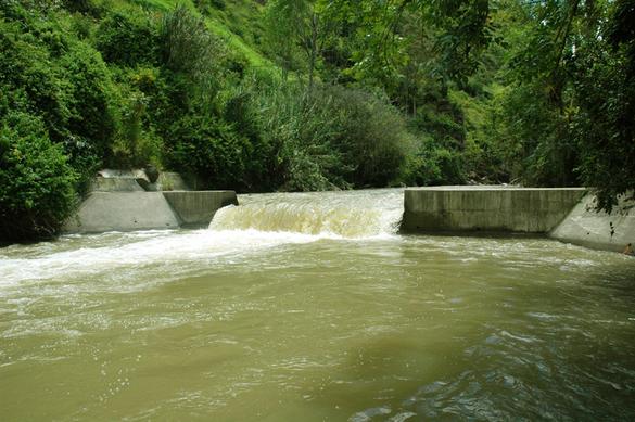
|
CHAPTER 6: CHANNEL DESIGN |
6.1 NONERODIBLE CHANNELS
There are two types of channels: (1) nonerodible, and (2) erodible. Nonerodible channels are typically lined
with a hard construction material, such as concrete or stone masonry. Erodible channels are dug on the ground surface and, therefore, directly in contact
with the underlying soil. The design of erodible channels is much more complex
than that of nonerodible channels.
The design of nonerodible channels begins with the choice of a uniform flow formula (Chapter 5).
The following factors are considered in the design of nonerodible channels:
Surface roughness
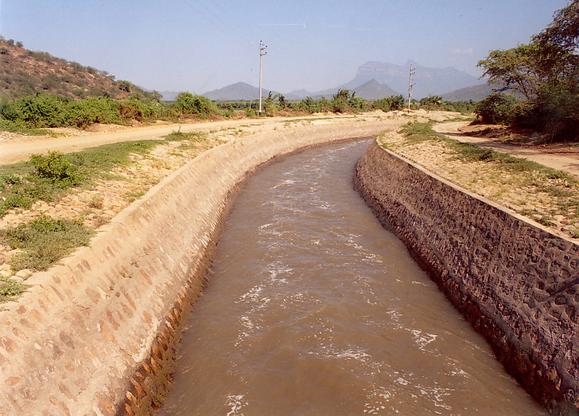
The surface roughness (boundary friction) is determined by the type and finish of the material lining the channel boundary.
Generally, coarser surfaces have higher friction than smoother surfaces (Fig. 6-1).
|
Fig. 6-1 A masonry-lined channel.
|
|
Minimum permissible velocity
All channels carry a certain amount of sediments (sand, silt, clay). Therefore,
flow in channels of very mild bottom slope may lead to excessive sediment deposition.
Thus, a minimum permissible velocity, i.e., a minimum bottom slope, is needed to avoid clogging.
Maximum bottom slope
All nonerodible channels will have a tendency to develop roll waves if the Vedernikov V > 1 (Chapter 1).
To avoid roll waves, the bottom slope must be kept below a maximum value which is a function of the hydraulics
of the flow.
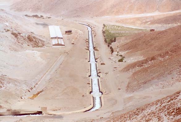
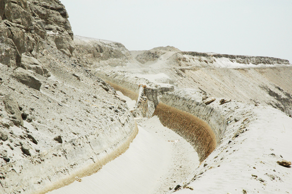
For instance, Fig. 6-2 shows a series of drops implemented in a channel to reduce the bottom slope.
|
Fig. 6-2 Channel drops implemented in a channel to decrease the channel slope,
La Joya Canal, Arequipa, Peru.
|
|
Shape of the cross section
The channel section of maximum conveyance and, therefore, maximum discharge,
is that which has the minimum wetted perimeter for a given flow area.
This shape of cross section is referred to as the best hydraulic section.
The best hydraulic circular section is a semicircle.
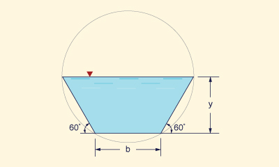
The best hydraulic trapezoidal section is a half regular hexagon inscribed in a circle (Chow, 1959)
(Fig. 6-3). In practice, however, other design considerations are usually more important
than that of maximum conveyance.
|
Fig. 6-3 Best hydraulic section of trapezoidal shape.
|
|
Side slopes
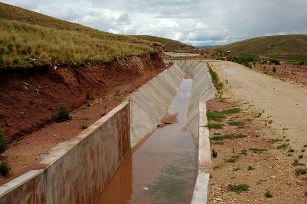
The side slope is z H : 1 V, wherein z = 0 for a rectangular section and z > 0 for a trapezoidal section, is a design decision that varies with local conditions (Fig. 6-4). Typical side slopes vary from z = 0 to z = 3.
|
Fig. 6-4 Channel transition from rectangular to trapezoidal shape.
|
|
Freeboard
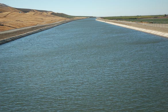
The freeboard is the vertical depth measured above the design channel depth, up to the total channel depth (Fig. 6-5).
It is intended to account for a safety factor and to minimize
wave overtopping.
|
Fig. 6-5 Freeboard in the San Luis Canal, California.
|
|
Slide risk reduction
In hillslope alignments,
care should be taken to reduce
the risk of
local slides, which, depending on their extent,
may render the channel inoperable.
Some hillslopes are prone to slides, while others are not.
A thorough geological/geotechnical site investigation is required to reduce the risk of slides.
Figure 6-6 shows a slide-generated breach in the La Cano Canal,
Arequipa, Peru, which occurred on November 4, 2010 (see
related video).
|
Fig. 6-6 Slide-generated breach, La Cano Canal,
Arequipa, Peru,
which occurred on November 4, 2010.
|
|
Channel lining
Channels or canals may be lined with one of several materials, including concrete, stone masonry, steel,
cast iron, timber, glass, and plastic.
Channel lining reduces boundary friction and minimizes channel maintenance costs.
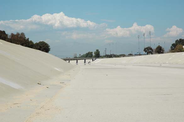
Figure 6-7 shows the Santa Ana river, at Huntington Beach,
California, paved with concrete to reduce flood stage and
control floods.
|
Fig. 6-7 Paved Santa Ana river, Huntington Beach,
California.
|
|
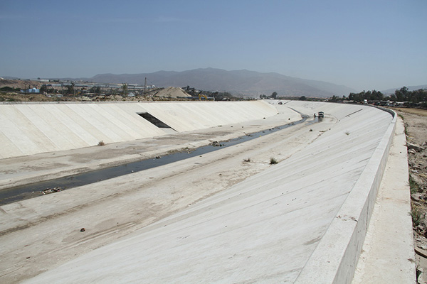
Figure 6-8 shows Alamar Creek, in Tijuana, Mexico, recently lined up with concrete (2013).
It is noted that current environmental design practices strongly discourage
the lining of natural channels
with concrete.
|
Fig. 6-8 Alamar Creek, Tijuana, Baja California, Mexico.
|
|
Minimum permissible velocity
All water carries a certain amount of suspended solids, in the form of sediments
that have entrained somewhere upstream and are being transported by the flow.
Typical values of suspended load are 200-300 parts per million (or ppm,
equivalent, at this range, to mg/L) (Ponce, 1989).
The no-slip condition at the channel boundary
(i.e., the local longitudinal velocity is zero at the channel boundary) produces shear stresses and
results in sediment entrainment.
Once entrained, this sediment
needs to be transported through the channel; otherwise, it will settle and eventually clog
the channel. The minimum velocity to avoid
settling/clogging is the minimum permissible velocity.
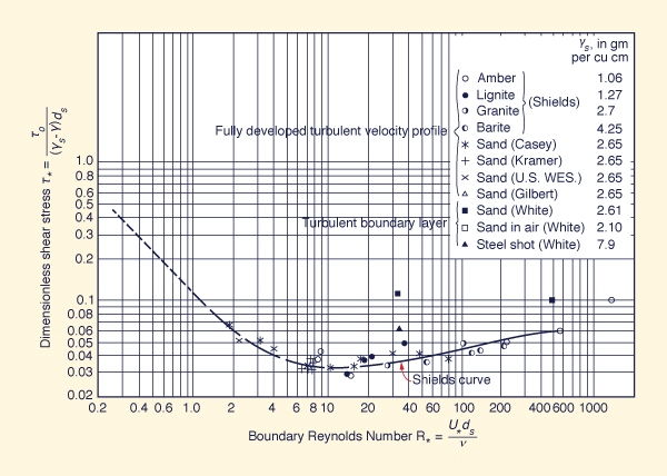
The evaluation of minimum permissible velocity may be accomplished with the Shields criterion for initiation of motion.
This criterion is embodied in the Shields diagram, shown in Fig. 6-9, which relates the dimensionless shear stress
τ*
with the boundary Reynolds number R*.
The solid curve in Fig. 6-9 separates
no motion (below the curve) from motion (above the curve).
|
Fig. 6-9 Shields diagram for initiation of motion (American Society of Civil Engineers, 1975).
|
|
Minimum Froude number and minimum permissible velocity
The quadratic friction law, Eq. 5-3, is recast here with τo as the bottom shear stress:
The Shields criterion for initiation of motion is:
τo
τ* = _____________ ≥
τ*c
(γs - γ ) ds
| (6-2)
|
in which τ*
= dimensionless shear stress, γs = specific weight of
sediment particles, γ = specific weight of water, ds = sediment
particle diameter, and
τ*c
= dimensionless critical shear stress.
Figure 6-9 shows the Shields curve, i.e., the variation of
dimensionless critical shear stress τ*c with the boundary Reynolds number
R*:
U* ds
R* = _________
ν
| (6-3)
|
in which U* = shear velocity = (τo /ρ)1/2 =
( f )1/2 V,
and ν = kinematic viscosity.
The Froude number F is:
V
F = ___________
(g D )1/2
| (6-4)
|
in which V = mean velocity, D = hydraulic depth, and g = gravitational acceleration.
Replacing Eqs. 6-1 and 6-4 into Eq. 6-2:
f D F 2
_____________________ ≥ τ*c
[ (γs / γ ) - 1 ] ds
| (6-5)
|
In most cases of practical interest, the ratio of specific weights of sediment and water
γs /γ is equal to 2.65. Therefore, in terms of Froude number,
the Shields criterion for initiation of motion reduces to:
1.65
τ*c (ds / D )
F ≥ [ __________________ ] 1/2
f
| (6-6)
|
For practical applications, a constant value of dimensionless critical shear stress
τ*c = 0.04
may be considered. From Fig. 6-9, it is seen that this value
encompasses the range: 4 ≤ R* ≤ 60. Therefore:
0.066
(ds / D )
F ≥ [ ________________ ] 1/2
f
| (6-7)
|
Equation 6-7 is the practical Shields-based Froude criterion for initiation of motion, applicable through a wide range of boundary Reynolds numbers.
As a practical example of the use of Eq. 6-7,
assume ds = 0.4 mm, D = 1 m, and a midrange dimensionless Chezy friction factor
f = 0.0035 (equivalent to a Darcy-Weisbach friction factor f = 0.028).
The application of Eq. 6-7 leads to:
Combining Eqs. 6-4 and 6-7:
0.066
(g ds)
V ≥ [ ______________ ] 1/2
f
| (6-9)
|
From Eq. 6-9, the minimum permissible velocity for this flow condition is: Vmin = 0.27 m/s.
A somewhat more precise value of minimum Froude number and minimum permissible velocity
may be obtained by using the actual value of dimensionless critical shear stress in Eq. 6-7,
in lieu of the convenient approximation τ*c = 0.04.
This procedure, however, requires an iteration.
For this purpose, the following algorithm is suggested:
Assume R*
Using Fig. 6-9, find
τ* = τ*c
With τ*,
use Eq. 6-2 to solve for τo
- Using Eq. 6-1, calculate the shear velocity U* = (τo /ρ)1/2
Using Eq. 6-3, calculate the new value of R*
Stop if the new value of R* is the same as that assumed in Step 1 (within a certain small tolerance), and use the last
value of τ*c (calculated in Step 2) in Eq. 6-6;
Otherwise, return to Step 1, using the new value of R* as the assumed value, and repeat the iteration.
|
Example 6-1.
Assume the following channel data: particle diameter ds = 0.4 mm, hydraulic depth D = 1 m, dimensionless Darcy-Weisbach friction factor
f = 0.0035, and water temperature T = 20°C.
Using the Shields criterion for initiation of motion, calculate the minimum Froude number and minimum permissible velocity.
 | |
ONLINE CALCULATION. Using
ONLINE SHIELDS VELOCITY,
the minimum Froude number is Fmin = 0.081, and the minimum permissible velocity is Vmin = 0.25 m/s.
Note that this result is slightly less than that obtained using Eqs. 6-7 and 6-9.
|
|
|
Channel slope
The design channel slope is usually governed by the chosen alignment and prevailing topography.
The actual design channel slope may depend on the purpose of the channel. For example, channels used for
irrigation and hydropower require small slopes, in order not to lose too much head during conveyance.
Side slopes depend on local soil and construction conditions, usually as steep as practicable.
For lined canals, a side slope of 1.5 H : 1 V is recommended as a standard by the U.S. Bureau of Reclamation, for use in most canals.
For lined canals and steep slopes, when the Vedernikov number exceeds 1, the possibility
arises for the development of roll waves (Chapter 1).
Freeboard
Freeboard is the vertical distance from the top of the channel to the water surface at the design condition. This distance
should be sufficient to prevent waves or fluctuations in the water surface from overflowing the channel sides.
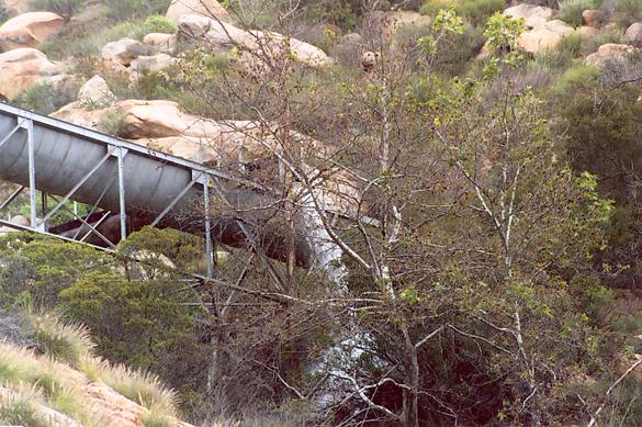
This feature becomes important, particularly in the design of elevated flumes, for the flume substructure may be endangered
by an overflow (Fig. 6-10).
|
Fig. 6-10 The Dulzura conduit, in San Diego County, California,
overflowing after heavy rain, on March 5, 2005.
|
|
There is no universally accepted rule for the determination of freeboard.
Wind-generated waves or tidal action may induce high waves, which would need to be kept within channel bounds.
Freeboards ranging from less than 5% to more than 30% of the design flow depth are in common practice.
For smooth, interior, semicircular flumes on tangents, carrying water at velocities no greater than the critical
velocity, with a maximum of 8 ft/s (2.4 m/s),
experience has indicated that a freeboard of 6% of the flume diameter is appropriate.
For flumes on curves, freeboard must be increased to prevent water from sloping over (Chow, 1959).
Note that hydraulic design criteria commonly allow for the use of all or part of the freeboard to accomodate the
Probable Maximum Flood (Ponce, 1989).
According to the U.S. Bureau of Reclamation, the approximate range
of freeboard extends from 1 ft (0.3 m)
for small laterals with shallow depths, to 4 ft (1.2 m) in canals up to 3,000 cfs (85 m3/s) or more.
The following formula is applicable:
in which Fb = freeboard, in ft; y = depth of water in the canal, in ft; and C = coefficient,
varying from C = 1.5
for a canal capacity of 20 cfs (0.57 m3/s) to C = 2.5 for a canal capacity of 3,000 cfs (85 m3/s) or more.
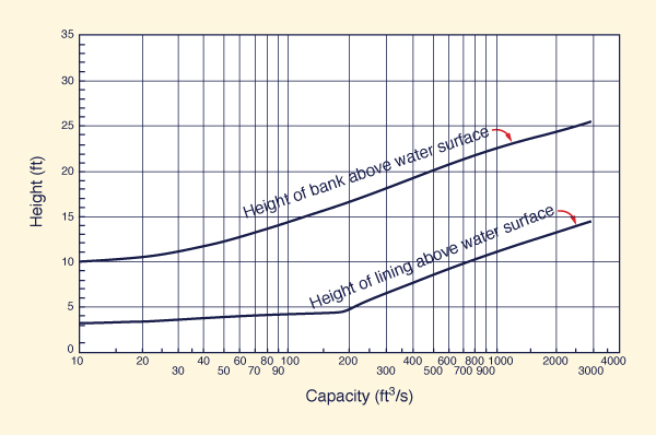
Figure 6-11 shows U.S. Bureau of Reclamation recommended
height of lining and height of bank, applicable for the design of freeboard.
|
Fig. 6-11 U.S. Bureau of Reclamation recommended
height of lining
and height of bank (Chow, 1959).
|
|
Section dimensions
The following steps are taken to choose the dimensions of a channel or canal cross section:
Select the design discharge Q
Select the bottom width b
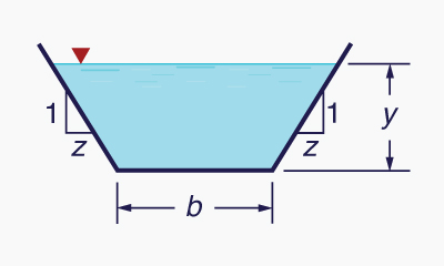
Select the side slope z [z H : 1 V] (Fig. 6-12)
|
Fig. 6-12 Definition sketch for bottom width b and side slope z.
|
|
Select the bottom slope S
Estimate the value of Manning's n (Chapter 5: Manning's n)
Using Q,
b, z, S, and n [Steps 1 to 5],
compute the normal depth yn, normal velocity
vn, and normal Froude number Fn
(Chapter 5: Computation)
Check to see if the normal velocity vn and normal Froude number Fn
are large enough to avoid clogging of the canal with sediment (see Minimum permissible velocity in this Chapter)
Select an appropriate freeboard Fb .
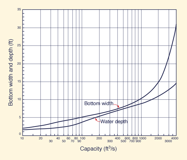
Figure 6-13 shows U.S. Bureau of Reclamation recommended
bottom width and water depth of lined channels.
|
Fig. 6-13 U.S. Bureau of Reclamation recommended
bottom width and water depth
of lined channels (Chow, 1959).
|
|
Example 6-2.
Design a channel for the following flow conditions: Q = 10 m3/s; b = 5 m; z = 2; S = 0.0016; n = 0.025.
Using Eq. 5-55, by iteration, the normal depth is yn = 1.049 m and the normal velocity is vn = 1.342 m/s.
The Froude number based on normal depth is Fn = 0.418.
The calculated Froude number is shown to be much larger than 0.087 (Eq. 6-8), the minimum value required to avoid sediment deposition.
A freeboard Fb = 0.6 m is assumed.
 | |
ONLINE CALCULATION. Using the
ONLINECHANNEL01 calculator,
the normal depth is yn = 1.049 m; the normal velocity is vn = 1.342 m/s;
the Froude number (based on hydraulic depth D = 0.81 m) is: Fn = 0.476.
|
|
Note that the true Froude number is that based on hydraulic depth (Eq. 4-6). For a hydraulically wide channel, for which
D ≅ R, both Froude numbers are approximately the same.
|
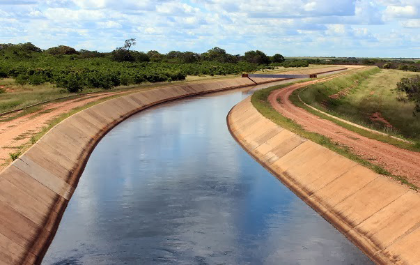
Figure 6-14 shows a major canal built in 1993 in Ceara, Brazil, for the purpose of mitigating a regional drought.
The hydraulic characteristics are: Q = 8.32 m3/s, b = 5 m, z = 1.5, S = 0.00005, and n = 0.015.
Using the
ONLINECHANNEL01 calculator,
the normal depth is yn = 1.915 m, the normal velocity is vn = 0.552 m/s, and
the Froude number is Fn = 0.149.
| Cogerh |
Fig. 6-14 The Workers' Channel (Canal do Trabalhador), Ceara, Brazil (1993).
6.2 ERODIBLE CHANNELS
The design of an erodible channel is much more complex than that of a nonerodible channel.
The long-term stability of the channel boundary depends on the properties of the material lining the boundary (sand, silt, clay, and combinations thereof),
and of the properties of the sediment being transported by the flow. Changes in water and sediment discharge
result in cross-sectional changes, either channel depth, channel width, or both.
The stability of the channel boundary is normally assessed in terms of two criteria:
Maximum permissible velocity, and
Maximum permissible tractive stress.
Given Eq. 6-1, these two methods are related as follows:
τo max = ρ f (Vmax )2
| (6-11) |
Example 6-3.
Calculate the maximum permissible velocity
corresponding to a maximum permissible tractive
stress of 20 N/m2.
Assume f = 0.0035, i.e., Darcy-Weisbach f = 0.028.
Using Eq. 6-11:
Vmax = [τo max / (ρ f ) ] 1/2 =
[ 20 N/m2 / (1000 N s2/m4 × 0.0035 ) ] 1/2 = 2.39 m/s.
|
Example 6-4.
Calculate the maximum permissible velocity
corresponding to a maximum permissible tractive stress of 0.1 lb/ft2.
Assume f = 0.005, i.e., Darcy-Weisbach f = 0.04.
Using Eq. 6-11:
Vmax = [τo max / (ρ f ) ] 1/2 =
[ 0.1 lb/ft2 / (1.94 lbs-s2/ft4 × 0.005 ) ] 1/2 = 3.21 ft/s.
|
Vegetative channels
Table 6-1 shows typical values of maximum permissible tractive stress for various types of vegetative channel linings.
|
Table 6-1 Typical values of maximum permissible tractive stress.
|
| Channel lining |
Maximum permissible
tractive stress | | (N/m2) |
(lb/ft2) |
| Lawn (short-time loaded) |
20-30 |
0.42-0.63 |
| Lawn (long-time loaded) |
15-18 |
0.31-0.38 |
| Fascine sausage |
60-70 |
1.25-1.46 |
| Fascine roll |
100-150 |
2.09-3.13 |
| Weighted fascine |
60-100 |
1.25-2.09 |
| Brush mattress |
150-300 |
3.13-6.26 |
| Live staking in rip rap |
> 140 |
> 2.92 |
| Willows/alder |
80-140 |
1.67-2.92 |
| Gabions |
80-140 |
1.67-2.92 |
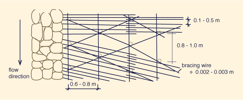
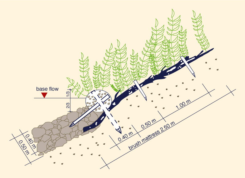
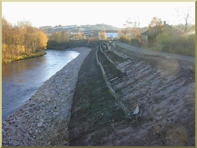
Figure 6-15 shows details of the design of a channel lining using a brush mattress.
|
Fig. 6-15 (a) Design of brush mattress: Top view.
|
|
|
Fig. 6-15 (b) Design of brush mattress: Side view.
|
|
|
Fig. 6-15 (c) Design of brush mattress: Side view after a few months.
|
|
|
Fig. 6-15 (d) Design of brush mattress: View after project completion.
|
|
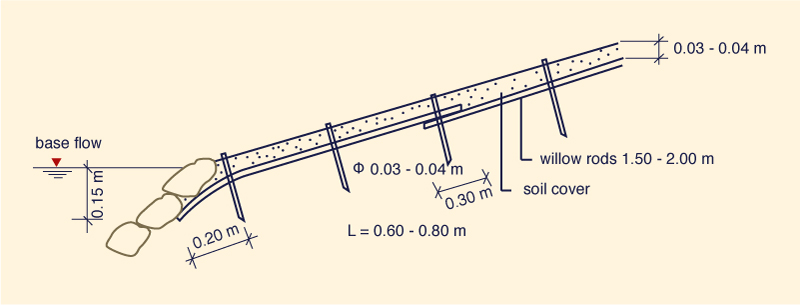
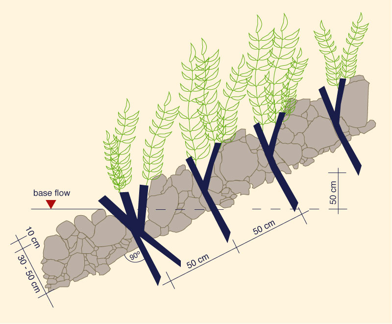
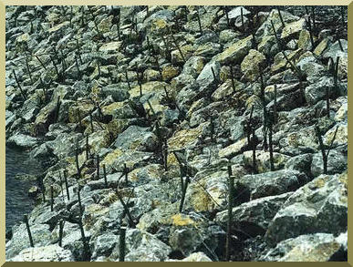
Figure 6-16 shows details of a channel lining using live staking in riprap.
|
Fig. 6-16 (a) Live staking: Schematic.
|
|
|
Fig. 6-16 (b) Live staking: Soon after installation.
|
|
|
Fig. 6-16 (c) Live staking: Sometime after installation.
|
|
|
Fig. 6-16 (d) Live staking: 2-5 years after installation.
|
|
|
Fig. 6-16 (e) Live staking: Established project.
|
|
Gabion-lined channels
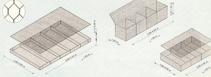
A gabion system is wire-enclosed riprap consisting of mats or baskets fabricated with wire mesh, filled with small
riprap, and anchored to a slope (Fig. 6-17). Wrapping the
riprap enables the use of smaller stone sizes for the same resistance to displacement by water energy. This is a particular advantage
when constructing rock lining in areas of difficult access. The wire basket also allows steeper (up to vertical) channel linings
to be constructed from commercially available wire units or from wire-fencing material.
|
Fig. 6-17 Placement of gabion mattress.
|
|
Gabion systems provide an effective way to control erosion in streams, rivers and canals.
They are normally designed to sustain large channel velocities [5 m/s (15 ft/s) or higher]. Gabions are
constructed by individual units that vary in length from 2 m (6 ft)
to nearly 30 m (100 ft); therefore, applications can range
anywhere from small ditches to large canals (Fig. 6-18).
|
Fig. 6-18 Dimensions of gabions boxes and mattresses.
|
|
Gabion channels are a compromise between riprap and concrete channels.
When the same-size rocks are used in gabions and riprap, the acceptable velocity for gabions is three to four times that of riprap.
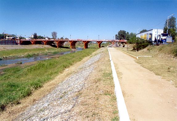
Unlike concrete, gabions can be
vegetated to blend into the natural landscape (Fig. 6-19).
Gabion channels with vegetation have the following advantages:
Allow infiltration and exfiltration
Filter out contaminants
More flexible than paved channels
Provide greater energy dissipation than concrete channels
Improve habitat for flora and fauna
More aesthetically pleasing
Lower cost to install, although some maintenance is required.
Values of Manning's n
for gabion-lined channels are normally in the range 0.025 ≤ n ≤ 0.030.
|
Fig. 6-19 Established channel lining with gabions.
|
|
6.3 TRACTIVE FORCE
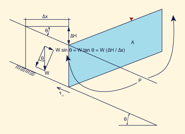
The tractive force is the summation of the (tractive) shear stresses over (an area of) the channel boundary.
Under equilibrium conditions, to develop the tractive stress equation,
the acting gravitational force is made equal to the resisting frictional force. The gravitational force is (Fig. 6-20):
W sin θ ≅ W tan θ = W (ΔH /Δx )
| (6-12) |
in which W = weight of the control volume of area A and length Δx,
ΔH = drop within the control volume,
and θ = channel bottom slope.
|
Fig. 6-20 Definition sketch for derivation of the tractive force equation.
|
|
Since S = ΔH /Δx, it follows that the acting gravitational force is:
The resisting frictional force is:
in which τo = bottom shear stress, and P = wetted perimeter.
Equating gravitational and frictional forces:
in which R = A /P = hydraulic radius.
For hydraulically wide channels, for which R ≅ D ≅ y,
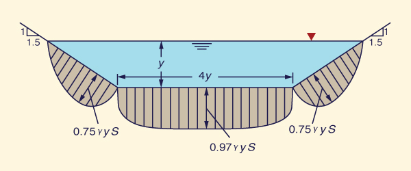
The tractive stress varies along the wetted perimeter, reaching a peak value along the
middle of the channel. Figure 6-21 shows a typical variation for a trapezoidal cross section, in which b/y = 4 and z = 1.5.
|
Fig. 6-21 Variation of tractive stress in a trapezoidal channel, with b/y = 4 and z = 1.5 (Chow, 1959).
|
|
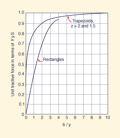
At the bottom center,
the tractive stress approaches asymptotically
its full (maximum) value: τb = γyS , as shown
in Fig. 6-22.
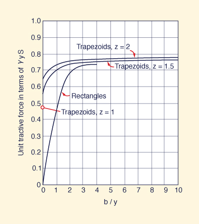
Along the channel sides, the tractive stress
approaches asymptotically a fraction of the full value: τs = 0.78 γyS , as shown in
Fig. 6-23.
|
Fig. 6-22 Variation
of maximum tractive stress on channel bottom
with aspect ratio b/y (Chow, 1959).
|
|
|
Fig. 6-23 Variation
of maximum tractive stress on channel sides
with aspect ratio b/y (Chow, 1959).
|
|
Tractive force ratio
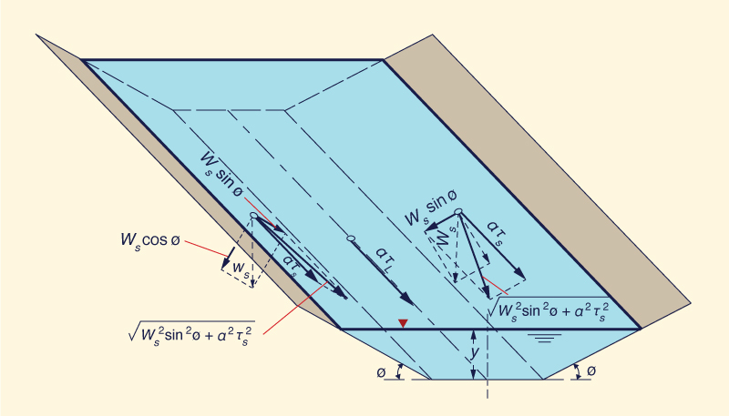
Figure 6-24 shows three particles on the channel boundary, one on the left side, another on the right side, and the third one
on level ground (bottom). The tractive force ratio K is defined as:
a τs τs
K = _______ = ______
a τL τL
| (6-17)
|
in which a = effective area of the particle, τs = shear stress
on the side, and τL = shear stress on level ground.
|
Fig. 6-24 Definition sketch
for the forces acting on a particle resting on the surface
of a channel bed (Chow, 1959).
|
|
Define θ as the angle of repose of the material forming the channel boundary
(note that θ is not shown explicitly in Fig. 6-24).
The ratio K is a function of the channel side slope φ and of the angle of repose θ of the material.
To derive K, consider the two forces that are acting on a particle of submerged weight Ws
resting on the side of the channel, with tractive stress τs:
The tractive force: aτs
The gravitational force component along the side: Ws sin φ
The resultant force acting along the side plane is:
Fa = (Ws2
sin2φ + a2τs2)1/2
| (6-18) |
At equilibrium, the resisting force is equal to the acting force. From solid mechanics, the resisting force is equal to the
normal force (Ws cosφ )
times the coefficient of friction (tanθ ):
Therefore:
Ws cosφ tanθ = (Ws2
sin2φ + a2τs2)1/2
| (6-20) |
Squaring both sides:
Ws2 cos2φ tan2θ = Ws2
sin2φ + a2τs2
| (6-21) |
a2τs2 = Ws2 cos2φ tan2θ - Ws2
sin2φ
| (6-22) |
τs2 = (Ws /a)2 cos2φ tan2θ - (Ws /a)2
sin2φ
| (6-23) |
tan2φ
τs2 = (Ws /a)2 cos2φ tan2θ [ 1 -
_________ ]
tan2θ
| (6-24) |
tan2φ
τs = (Ws /a) cosφ tanθ [ 1 -
_________ ] 1/2
tan2θ
| (6-25) |
Equation 6-25 is the shear stress on the side of a channel with side slope angle φ and repose angle θ.
For a level surface, with φ = 0:
sinφ = 0 and cosφ = 1. Thus, the force balance of Eq. 6-20 reduces to:
Therefore, the shear stress that causes impending motion on a level surface is:
Combining Eqs. 6-17, 6-25, and 6-27, the tractive force ratio is:
tan2φ
K = cosφ [ 1 -
_________ ] 1/2
tan2θ
| (6-28) |
It is seen that K is only a function of φ and θ. Equation 6-28 is equivalent to (See box below):
sin2φ
K = [ 1 -
__________ ] 1/2
sin2θ
| (6-29) |
Derivation of Eq. 6-29
Equation 6-28 is simplified by resorting to established trigonometric identities:
tan2φ
K = cosφ [ 1 -
_________ ] 1/2
tan2θ
| (6-28a) |
cos2φ tan2φ
K = [ cos2φ -
________________ ] 1/2
tan2θ
| (6-28b) |
sin2φ
K = [ cos2φ -
_________ ] 1/2
tan2θ
| (6-28c) |
sin2φ cos2θ
K = [ cos2φ -
________________ ] 1/2
sin2θ
| (6-28d) |
sin2φ (1 - sin2θ)
K = [ 1 - sin2φ -
_____________________ ] 1/2
sin2θ
| (6-28e) |
sin2φ
K = [ 1 -
__________ ] 1/2
sin2θ
| (6-29) |
|
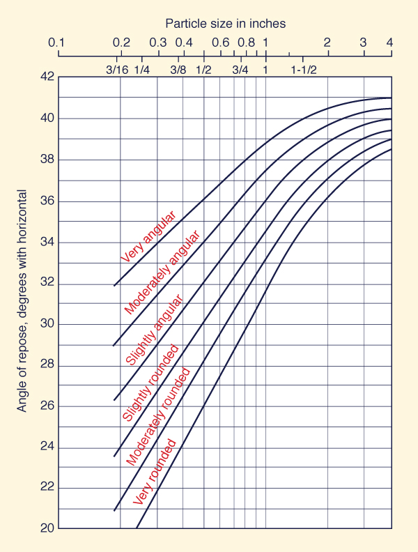
Angle of repose
Figure 6-25 shows the angle of repose of noncohesive materials, i.e., the angle θ in Eq. 6-29.
The particle size (in inches) is that for which 25% of the material, by weight, is larger.
|
Fig. 6-25 Angle of repose
of noncohesive materials (Chow, 1959).
|
|
6.4 PERMISSIBLE TRACTIVE FORCE
The permissible tractive force (unit force, or stress) method is used in the design of
erodible channels and canals.
The permissible unit tractive force is the maximum shear stress
that will not cause erosion of the material forming the channel bed on a level surface. The value, obtained
from laboratory experiments, is referred to as the critical unit tractive force, or critical shear stress.
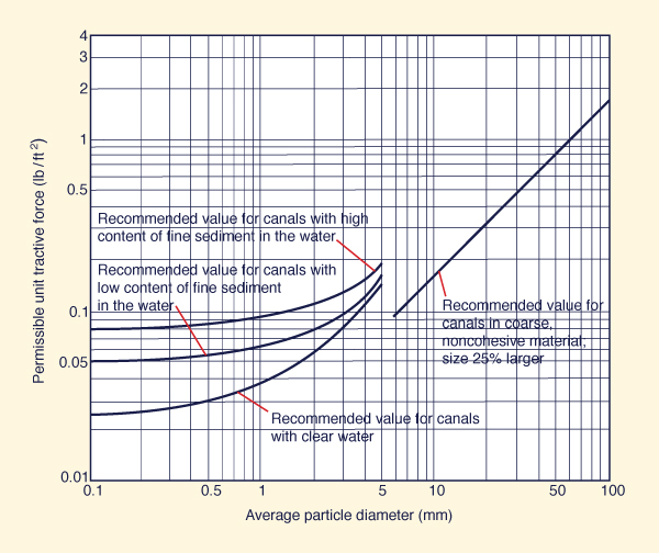
Figure 6-26 shows permissible unit tractive force (unit tractive stress) for canals in noncohesive materials.
The figure applies through a range of (average) particle diameter from 0.1 to 100 mm.
The left side of the graph applies for fine noncohesive material (sand), with diameter ranging from 0.1 to 5 mm. Three curves are shown:
The upper curve, applicable for canals with high content of fine sediment
(silt) in the water;
The middle curve, applicable for canals with low content of fine sediment
(silt) in the water;
The lower curve, applicable for canals with clear water.
Note that the cleaner the water, the more likely it is to pick up sediment from the boundary and, therefore,
the lower the value of the permissible unit tractive force.
The right side of Fig. 6-26 applies for canals in coarse noncohesive material, with diameter ranging from
5 to 100 mm (fine to very coarse gravel, to small cobbles). The line shown in Fig. 6-26
is equal to 0.4 times the particle diameter (in inches) for which 25% of the material is larger,
by weight, i.e., the permissible unit tractive force, or permissible tractive stress, is equal
to
0.4 × d25 (in).
|
Fig. 6-26 Permissible unit tractive force for canals in
noncohesive materials (Chow, 1959).
|
|
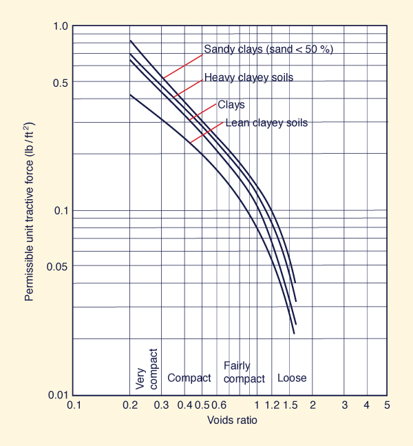
For cohesive materials, the critical shear stress is a function of the type of soil (sandy clays to lean clays)
and the voids ratio, as shown in Fig. 6-27.
|
Fig. 6-27 Permissible unit tractive force for canals in
cohesive materials (Chow, 1959).
|
|
The values of Figs. 6-26 and 6-27 are applicable to straight channels.
For sinuous channels, the values shown in the figures should be reduced to account for bank scour.
Table 6-2 shows recommended percentage reduction in critical shear stress
to account for channel sinuosity.
Table 6-2 Reduction in critical shear stress
to account for channel sinuosity.
|
| Sinuosity |
Reduction
(%) |
| Low |
10 |
| Moderate |
25 |
| High |
40 |
Permissible tractive force method
The permissible tractive force method is a method to design erodible channels
based on the estimated critical shear stress for the material(s) forming the channel boundary. The value of critical shear stress is determined
experimentally or from established experience. The computational procedure is described below,
along with a worked example, for two possible cases:
Use of the
same material
on sides and bottom, and
Use of one material on the sides
and another on the bottom.
A. The same
material on sides and bottom
Input data: Discharge Q, side slope z, channel slope S, and Manning's n; particle d25 and grain shape; material on sides and bottom are
the same.
Assume b/y = 6, i.e., a reasonable value to start.
Assume that
the tractive force on the sides is controlling the design. This is the usually case when
the material on the sides and bottom are the same.
With b/y and z, enter Fig. 6-23 to determine the value of
Cs (Cs is the ordinate of Fig. 6-23) on the expression for the acting unit tractive force on the sides:
Ts = Cs γ y S.
With d25 and grain shape, use Fig. 6-25 to find the angle of repose θ.
Calculate side slope: φ = tan-1 (1/z)
Use Eq. 6-29 to calculate K.
Use Fig. 6-26 to determine the permissible unit tractive force on level ground τL.
Calculate the permissible unit tractive force on the sides: τs = K τL.
Set the permissible unit tractive force
greater than or equal to the acting unit tractive force: τs ≥ Ts; i.e.,
τs ≥ Cs γ y S
Solve for flow depth: y = τs / (Cs γ S)
Calculate b: b = (b/y) y
With Q, b, z, n, and S known, solve for normal depth yn.
Test to confirm that yn ≤ y. If not, assumed value of b/y is too small.
Assume a larger value and return to Step 11 and iterate. Once satisfied, set y = yn and go to next step.
With last b/y and z, enter Fig. 6-22 to determine the value of
Cb (the ordinate of Fig. 6-22) on the expression for the acting unit tractive force on level ground TL = Cb γ y S.
Calculate TL = Cb γ yn S
Compare TL calculated in Step 15 with τL calculated in Step 7.
If TL ≤ τL, the sides control the design, as initially assumed. Stop here.
|
A. Worked example
Input data: Q = 600 cfs; z = 2, channel slope S = 0.001, and Manning's n = 0.022; particle d25 = 0.7 in, and slightly angular grain shape;
material on sides and bottom are the same.
Assume b/y = 6.
Assume that the tractive force on the sides is controlling the design.
With b/y = 6
and z = 2, enter Fig. 6-23 to determine the value of
Cs = 0.78.
With d25 = 0.7 in
and slightly angular grain shape, use Fig. 6-25 to find θ = 34°.
φ = tan-1 (1/z) = 26.565°
Use Eq. 6-29 to calculate K = 0.6.
Use d25 = 0.7 inches in Fig. 6-26 to determine τL = 0.28 lb/ft2.
τs = K τL = 0.6 × 0.28 = 0.168 lb/ft2.
Set the permissible unit tractive force greater than or equal to the
acting unit tractive force:
τs = 0.168 ≥ Cs γ y S = (0.78) (62.4) y (0.001)
Solve for flow depth: y ≤ 3.45 ft.
Set y = 3.45 as the target flow depth.
b = (6) (3.45) = 20.7. Round to b = 21 ft.
With Q = 600, b = 21,
z = 2, n = 0.022, and
S = 0.001, solve for normal depth: yn = 4.536 ft.
yn = 4.536 > y = 3.45.
The width b is too short.
Assume (by trial and error) b/y = 10. b = (10) (3.45) = 34.5. Round to b = 35 ft.
With new b, solve for normal depth: yn = 3.376 ft.
Now yn < y. Set y = 3.376 ft and go to next step.
With b/y = 10
and z = 2, enter Fig. 6-22 to determine the value of
Cb = 1.0.
Calculate TL = (1.0) (62.4) (3.376) (0.001) = 0.211 lb/ft2.
Compare TL = 0.211 calculated in Step 15 with τL = 0.28 calculated in Step 7.
TL = 0.211 < τL = 0.28; therefore, the sides control the design, as initially assumed. Stop here.
|
| |
B. One material on the sides
and another on the bottom
Input data: Discharge Q, side slope z,
channel slope S, and Manning's n; material on sides and bottom are
different, specify type of material, particle size and grain shape, and fine sediment content if required.
Assume b/y = 6, i.e., a reasonable value to start.
Assume that
the tractive force on the sides is controlling the design. This is the usually case when
the material on the sides and bottom are the same.
With b/y and z, enter Fig. 6-23 to determine the value of
Cs (Cs is the ordinate of Fig. 6-23) on the expression for the acting unit tractive force on the sides:
Ts = Cs γ y S.
With d25 and grain shape, use Fig. 6-25 to find the angle of repose θ.
Calculate side slope: φ = tan-1 (1/z)
Use Eq. 6-29 to calculate K.
Use Fig. 6-26 to determine the permissible unit tractive force on level ground based on the material from the sides τLs (right of Fig. 6-26), and the permissible unit tractive force on level ground based
on the material from the bottom τLb (left of Fig. 6-26)
Calculate the permissible unit tractive force on the sides: τs = K τLs.
Set the permissible unit tractive force
greater than or equal to the acting unit tractive force: τs ≥ Ts; i.e.,
τs ≥ Cs γ y S
Solve for flow depth: y = τs / (Cs γ S)
Calculate b: b = (b/y) y
With Q, b, z, n, and S known, solve for normal depth yn.
Test to confirm that yn ≤ y. If not, assumed value of b/y is too small.
Assume a larger value and return to Step 11 and iterate. Once satisfied, set y = yn and go to next step.
With last b/y and z, enter Fig. 6-22 to determine the value of
Cb (the ordinate of Fig. 6-22) on the expression for the acting unit tractive force on level ground TL = Cb γ y S.
Calculate TL = Cb γ yn S
Compare TL calculated in Step 15 with τLb calculated in Step 7.
If TL ≤ τL, the sides control the design, as initially assumed. Instead, if TL > τL, the bottom controls the design.
If TL > τL, force TL = τL.
Solve for new y, confirming bottom control.
|
B. Worked example
Input data: Q = 600 cfs; z = 2, channel slope S = 0.001, and
Manning's n = 0.022; material on the sides: noncohesive, d25 = 0.7 in,
slightly angular grain shape; material on the bottom:
noncohesive, d60 = 0.8 mm, with
high content of fine sediment in the water.
Assume b/y = 6.
Assume that the tractive force on the sides is controlling the design.
With b/y = 6
and z = 2, enter Fig. 6-23 to determine the value of
Cs = 0.78.
With d25 = 0.7 in
and slightly angular grain shape, use Fig. 6-25 to find θ = 34°.
φ = tan-1 (1/z) = 26.565°
Use Eq. 6-29 to calculate K = 0.6.
Use Fig. 6-26 (right)
to determine τLs = 0.28 lb/ft2;
use Fig. 6-26 (left)
to determine τLb = 0.09 lb/ft2.
τs = K τLs = 0.6 × 0.28 = 0.168 lb/ft2.
Set the permissible unit tractive force greater than or equal to the
acting unit tractive force:
τs = 0.168 ≥ Cs γ y S = (0.78) (62.4) y (0.001)
Solve for flow depth: y ≤ 3.45 ft.
b = (6) (3.45) = 20.7. Round to b = 21 ft.
With Q = 600, b = 21,
z = 2, n = 0.022, and
S = 0.001, solve for normal depth: yn = 4.536 ft.
yn = 4.536 > y = 3.45.
The width b is too short.
Assume (by trial and error) b/y = 10. b = (10) (3.45) = 34.5. Round to b = 35 ft.
With new b, solve for normal depth: yn = 3.376 ft.
Now yn < y. Set y = 3.376 ft and go to next step.
With b/y = 10
and z = 2, enter Fig. 6-22 to determine the value of
Cb = 1.0.
Calculate TL = (1.0) (62.4) (3.376) (0.001) = 0.211 lb/ft2.
Compare TL = 0.211 calculated in Step 15 with τLb = 0.09 calculated in Step 7.
TL = 0.211 > τL = 0.09;
therefore, the bottom controls the design.
Force
TL = Cb γ yn S = (1.0) (62.4) y (0.001) = 0.09.
Therefore: y = 1.44 ft. Assume (by trial and error)
b/y = 106. Therefore: b = 154 ft.
With Q = 600, b = 152, z = 2, S = 0.001, and n = 0.022, calculate y = 1.44 ft. Design now OK!
|
| |
6.5 OTHER FEATURES
Other features in hydraulic channel design
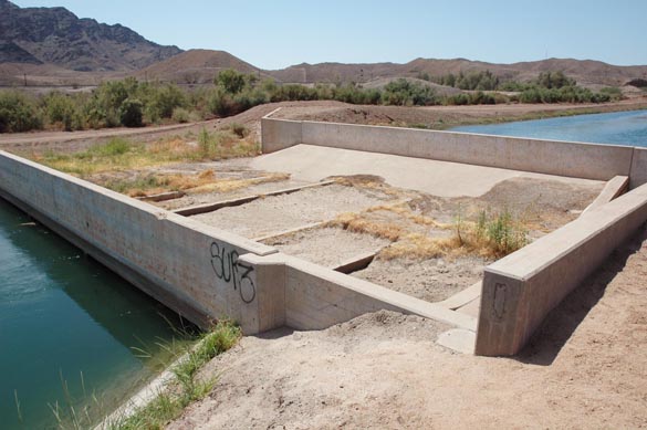
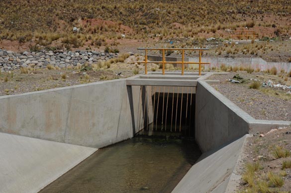
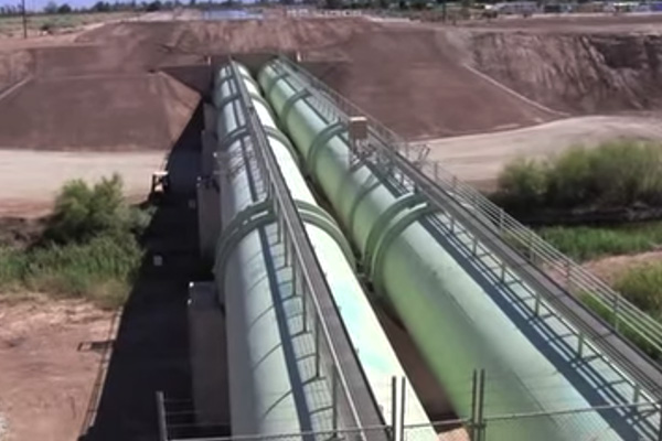
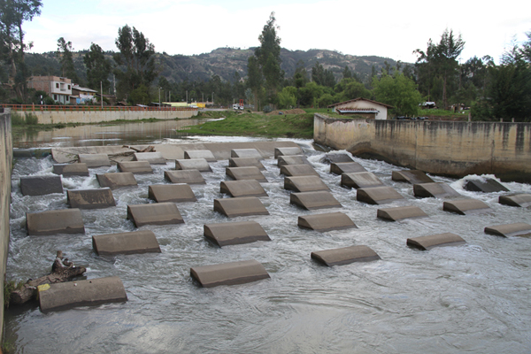
include canal drops and creek crossings, dissipation
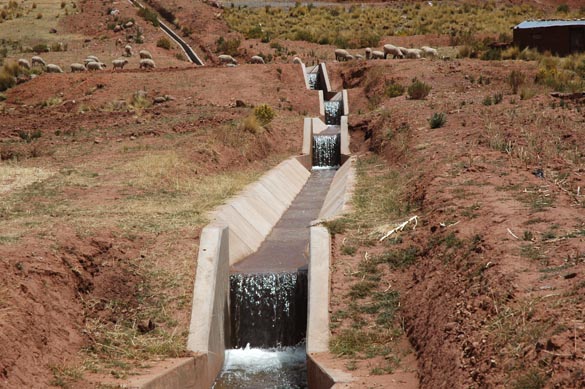
structures, and grade control structures. Figures 6-28 to 6-34 show
some illustrative examples.
|
Fig. 6-28 A series of canal drops
for the purpose of controlling flow instability,
Cabana-Maņazo
irrigation project, Puno, Peru.
|
|
|
Fig. 6-29 Crossing of
Tinajones feeder canal through
Chiriquipe Creek, Lambayeque, Peru.
|
|
|
Fig. 6-30 A small creek bypass,
Wellton-Mohawk Canal, Wellton, Arizona.
|
|
|
Fig. 6-31 A canal crossing a stream by means
of a siphon,
Cabana-Maņazo
irrigation project, Puno, Peru.
|
|
|
Fig. 6-32 Crossing between an irrigation and a drainage canal (top), Region 1, Guyana.
|
|
|
Fig. 6-33 Crossing of the New River
by the All-American Canal by means
of a large siphon, near Calexico, Imperial valley, California.
|
|
|
Fig. 6-34 Dissipation structure, Mashcon river,
Cajamarca, Peru.
|
|
|
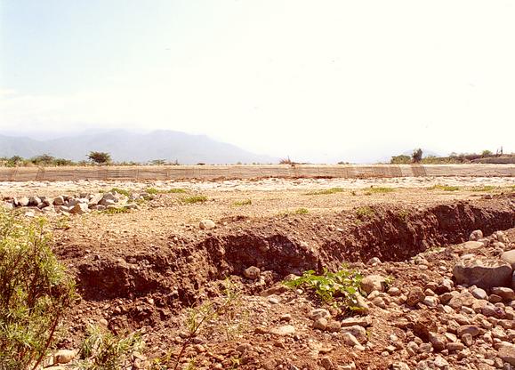
Fig. 6-35 Grade control structure, Caqueza river,
Cundinamarca, Colombia.
|
|
QUESTIONS
What determines the surface roughness
in an artificial canal?
What is the freeboard in the design of a canal?
What is the abscissa in the Shields diagram?
What is the ordinate in the Shields diagram?
What Froude number will generally assure initiation of motion?
How are the minimum and maximum permissible velocities
reconciled in a channel design?
How are the maximum permissible velocities and shear stresses
related?
What is the maximum value of the coeeficient Cs for shear stress
on the channel sides?
What is the range of angle of repose of noncohesive materials?
What is the tractive force ratio?
How does the content of fine sediment in the water affect the value of
permissible unit tractive force?
When is a grade control structure justified?
PROBLEMS
What is the minimum permissible velocity for a sediment particle diameter ds = 0.6 mm
and a dimensionless Chezy (modified Darcy-Weisbach) friction factor f = 0.004?
What is the minimum Froude number and minimum permissible velocity for a sediment particle diameter ds = 0.6 mm,
dimensionless Chezy friction factor f = 0.004, hydraulic depth D = 1 m, and water temperature T = 20°C?
What is the minimum Froude number and minimum permissible velocity for a sediment particle diameter ds = 0.3 mm,
dimensionless Chezy friction factor f = 0.003, hydraulic depth D = 3 ft, and water temperature T = 68°F?
A channel has the following data: Q = 330 cfs, z = 2, n = 0.025, and S = 0.0018.
Use the tractive force method to calculate the bottom width and depth under the following conditions:
- The particles are the same in sides and bottom; they
are moderately angular and of size d25 = 0.9 in.
- Same as in (a), but the particles are moderately rounded.
Discuss how the particle shape affects the design. Verify with ONLINE TRACTIVE FORCE.
A channel has the following data: Q = 220 m3/s, z = 2, n = 0.03, and S = 0.0006.
Use the tractive force method to calculate the bottom width and depth under the following conditions:
- The particles on the sides
are slightly angular and of size d25 = 35 mm; the particles on the bottom are of size d50 = 5 mm.
- The particles on the sides
are the same as in (a), but the particles on the bottom are smaller, of size d50 = 4 mm.
Both cases (a) and (b) have low content of fine sediment
in the water and the channel sinuosity is negligible.
Discuss how the bottom particle size affects the design. Verify with ONLINE TRACTIVE FORCE.
A certain type of lawn has a critical shear stress τc = 30
N/m2.
The dimensionless Chezy friction factor f = 0.0075.
What is a good estimate of the critical velocity?
REFERENCES
American Society of Civil Engineers, 1975. Sedimentation Engineering. Manual of Practice No. 54.
Chow, V. T. 1959. Open-channel Hydraulics. McGraw Hill, New York.
Ponce, V. M. 1989. Engineering Hydrology, Principles and Practices. Prentice Hall,
Englewood Cliffs, New Jersey.
| http://openchannelhydraulics.sdsu.edu |
|
201007 08:30 |
|
|
|
